10.6 ELECTRICAL SYSTEM
All rocket engines depend on some type of electrical system for their operation. This is true for solid systems, where at least ignition is initiated electrically, as well as or liquid systems, in which the electrical system assumes numerous additional tasks. As with any common household device, electrical circuits in rocket engines have caused troubles, due to poor design, misapplication, abuse, poor maintenance, human errors, and wear. Properly applied, however, electrical circuits car substantially simplify the operation of a rocket engine, and will increase its usefulness and reliability. There are many tasks, such as sequencing which can be accomplished much more effectively electrically than would be possible by mecharical means.
It is not possible nor necessary, in the framework of this book, to describe the physical laws and the general fundameriais of electrical circuitry. They are covered abundantly in the literature. Moreover, ir contrast with most other baric liquid engine subsystems, the rocket engine designer will try to use commercialiy available "off the shelf" components for his electrical system. However, other cognizant members of the design team will have to provide the basic circuit diagram (schematic) and other data in support of the installation of the required electrical components. Characteristically, the electrical system of a rocket engine is one of the last subsystems to be "frozen" before production. This is because sequencing for start and stop revresents one of the major engine development activities, often resulting in repeated modification of the electrical system as development progresses. Emphasis is therefore placed on the flexibility of electrical design. More recently, this process has been greatly aided by dynamic analyses (see sec. 10.2).
Electrical Schematic
The complete electrical schematic of a typical liquid rocket engine system, including its ground- and vehicle based elements, filis a sizable drawing. With the aid of figure 10-13, which presents a portion of an earlier engine static-firing schematic, the basic features are discussed as follows. In ordinary wiring diagrams, such as that of a radio receiver, all the contacts of, for instance, a multiple switch or a tube are drawn to appear in the same location, as they do in reality. This requires numerous wire crossovers in the diagram. The number of crossovers would become prohibitive in a typical engine electrical schematic and may lead to confusion and errors. For rocket engine purposes it has long been found preferable to draw the basic diagram so as to show each circuit separately. In this "functional flow diagram," the various contacts oi a relay, for instance, appear in different places, and often away from the circuit for the corresponding relay coil. The
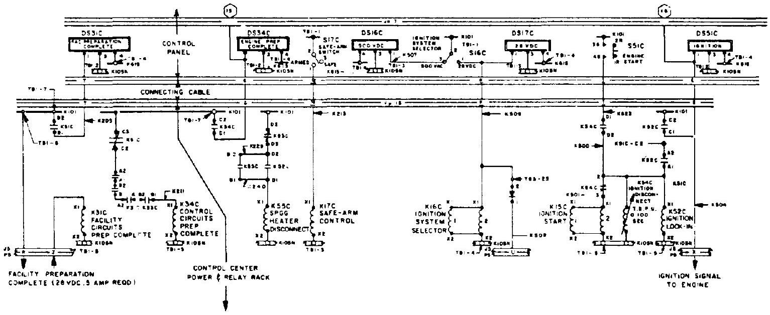 Figure 10-13.-Typical liquid rocket engine electrical diagram (partial).
drawing system also will materially simplify later troubleshooting. The diagram, of which figure shows a portion, was drawn sequentially from left to right; i.e., circuits which are energized during test preparation and start are shown in the left portion, while those associated with the cutoff sequence appear on the right.
In the schematic, connectors are shown as continuous double lines, or portions thereof, running horizontally through the diagram (J16, P16 = receptacle 16 and plug 16, etc.).
Each of the contacts is called out by a letter ( , etc.). All wires are numbered, as indicated. Power buses, like connectors, are shown as horizontal lines, or portions thereof (heavy, single line = positive buses, usually shown near the top of the drawing; and double lines = negative or ground bus). The meaning of the remaining symbols becomes clear by following the circuit at the left of figure 10-13. Plug P5 is shown connected to the main power bus K101 at terminal TB1-8. If certain facility signal contacts are properly closed, such as those verifying "Cooling water OK," "Firex armed," "Observer on Station," and many more, power returns through plug P5, contact "Z." and is applied to relay coil K 31 C . The " B " contact of this relay closes a circuit to lamp DS31C, which lights up. The "A" contacts of the same relay are in the chain to the coil of K34C, together with the normally open contacts of several other relays, such as K29C, "Heater Power On," and
K28C, "Hypergol Cartridge Installed," as well as the normally closed contacts of cutoff relay K91C. If all contacts are properly closed, the "C" contacts of K34C will cause signal light DS34C to light up. Following selection of the ignition power source by means of switch S16C, ignition can now be initiated by means of pushbutton S51C, since the "D" contacts of K34C are now closed, and provided ignition disconnect timer K54C has not picked up (TDPU = time delayed pickup : 0.1 sec ). In the diagram, several circuit elements appear which are part of other circuits not discussed. Note that in places two relays are used in parallel (e.g., K16C), if the number of contacts required is too large for one relay. The numbers shown in hexagonal frames refer to the channels of an inking sequence strip chart recorder or equivalent instrument. A special test bus K615 is provided which when energized makes all signal lights go on and thus permits spotting burnt-out bulbs.
In earlier engine designs, many of the elements shown in figure 10-13 were installed in an engine-mounted relay box. The trend has been to place as many parts of the electrical system on ground as possible. This is easier with first stages, which start while still connected to ground, or even held down mechanically until released, for brief periods following start, than it is with upper stages which must start and stop, and sometimes restart, some time after takeoff. Because of individual approach and of preferences for the types of interlocks, safeguards required, and type of component used, two designers of a comparable engine may arrive at substantially different electrical diagrams. Specifically with respect to the number of interlocks and monitoring circuits applied, caution is advised, since these circuit elements by themselves are subject to malfunction and may do more harm than good.
The diagram discussed above employed relays, well-developed types of which continue to be used in several of today's rocket engines. In others, solid-state (transistorized) switches are being applied which fulfill a similar function. Solid-state switches have the advantage of requiring no moving parts and thus are much less sensitive to vibration effects. A circuit of this type is shown in figure 10-14. It functions as follows:
Transistor is held in a "turned off" mode by maintaining the base at a higher voltage potential than the emitter. This is achieved by inserting a bias voltage, . As can be seen, as long as there is no appreciable current flow in , the base potential will be essentially , while that at the emitter is . Thus, will remain off.
Transistor is held in a "turned off" mode in a similar fashion, except that here the base
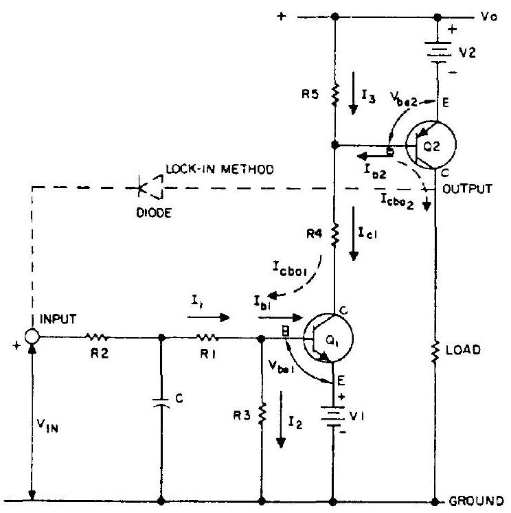 Figure 10-14.-Typical rocket engine solid-state switch circuit or "module" diagram.
must be at a lower potential than the emitter. This is accomplished by inserting a bias voltage, , in the emitter leg, which raises the emitter potential volts above ground. Again, as long as no appreciable current flows through and , the base will essentially be at ground potential, and will remain off.
When input voltage is applied, current will flow. This raises the base potential, until the combined base-emitter voltage, ( ), plus bias voltage ( ), is overcome. At this point, current will flow into the base ( ) causing the transistor to turn on. This occurs when
When turns on, resistor is switched to ground, and current begins to flow. As increases, the potential at the base of is lowered until it reaches the combined potential of and the base-emitter voltage, . At this point, current flows out of the base of and the transistor "turns on," thereby supplying current to the load. This occurs when
The switch is turned off by either removing the input signal, , or by using another static switch to ground the base of .
Switch lock-in (to maintain output after input signal is removed) is accomplished by feeding the output voltage back to the input through a diode. In this case, shorting the base of must be used to turn off the switch.
Figure 10-15 shows a typical solid-state switch module. Following assembly, a module is immersed in a potting compound. Overall module dimensions after potting are comparable to those of a matchbox.
Figure shows a small portion of an engine-mounted sequence-controller diagram. The modules shown, together with the others required for engine operation, including connecting wiring and connectors, are housed in a hermetically sealed box or can.
Although the two diagrams are not related, the signal emitted at pin X of receptacle J-5 in figure would be suitable to initiate engine start at contact A of plug P51 in figure 10-16. Similarly, the signal emitted from pin K of plug
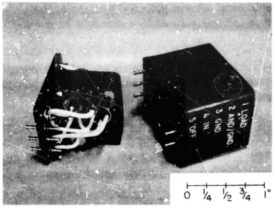 Figure 10-15.-Assembled solid-state switch module before and after potting.
P51 in figure 10-16, with the aid of an auxiliary relay, could be used to assure engine readiness in the chain leading to the coil of relay K34C in figure 10-13.
Electrical Components
To implement rocket engine electrical circuitry such as the one partially shown in figure 10-13, a number of components are required. These are:
Relays and Switches
Relays and, more recently, the solid state switches are used to receive usually low currunt command signals from the vehicle or ground control center and to translate them into properly sequenced actuation signals to igniters, control valves and other elements. In combination with interlocking relay contacts, bias voltages, valve position switches, continuity monitors, temperature sensors, spark plug monitors, voltage sensors, timers, and other devices, they form an engine-contained logic which will execute a sometimes elaborate starting sequence in response to only two external signals: start and stop. In practice many more signals are exchanged between engine and vehicle and/or
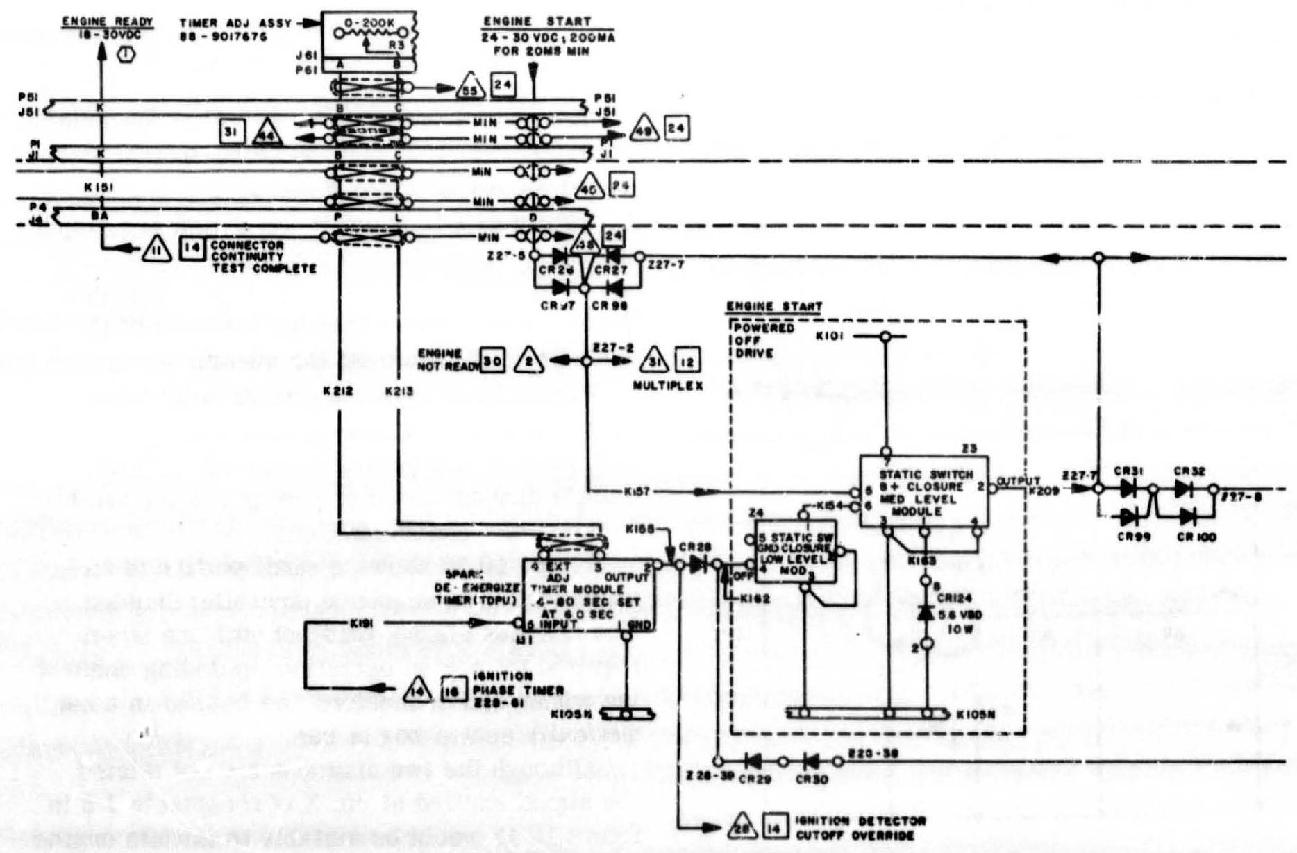 Figure 10-16.-Portion of a typical engine-mounted sequence controller diagram using solid-state switches.
ground control center, for checkout, monitoring, confirmation, instrumentation, telemetry and emergency reaction systems. Also, power supply connections are required.
The relays and switches, together with supporting circuitry elements such as resistors, capacitors, diodes, terminal strips, and connecting wiring, are best housed in a common box. This sequence controlier is hermetically sealed and often includes temperature-conditioning provisions by means of electrical heaters (typical power requirement: 200 watts) or inert gas purges. The engine systems designer very likely will receive from the cognizant department merely a "black box" description of the sequence controller, giving external and mounting bracket dimensions, connector descriptions, and installation specifications, with all internal detail omitted. Because of miniaturization, relay boxes or sequence controllers have become very compact units. Figure 10-17 shows a typical can. Note brackets for engine attachment. In addition to approximately 30 modules, numerous diodes, resistors, timers, etc., the container shown
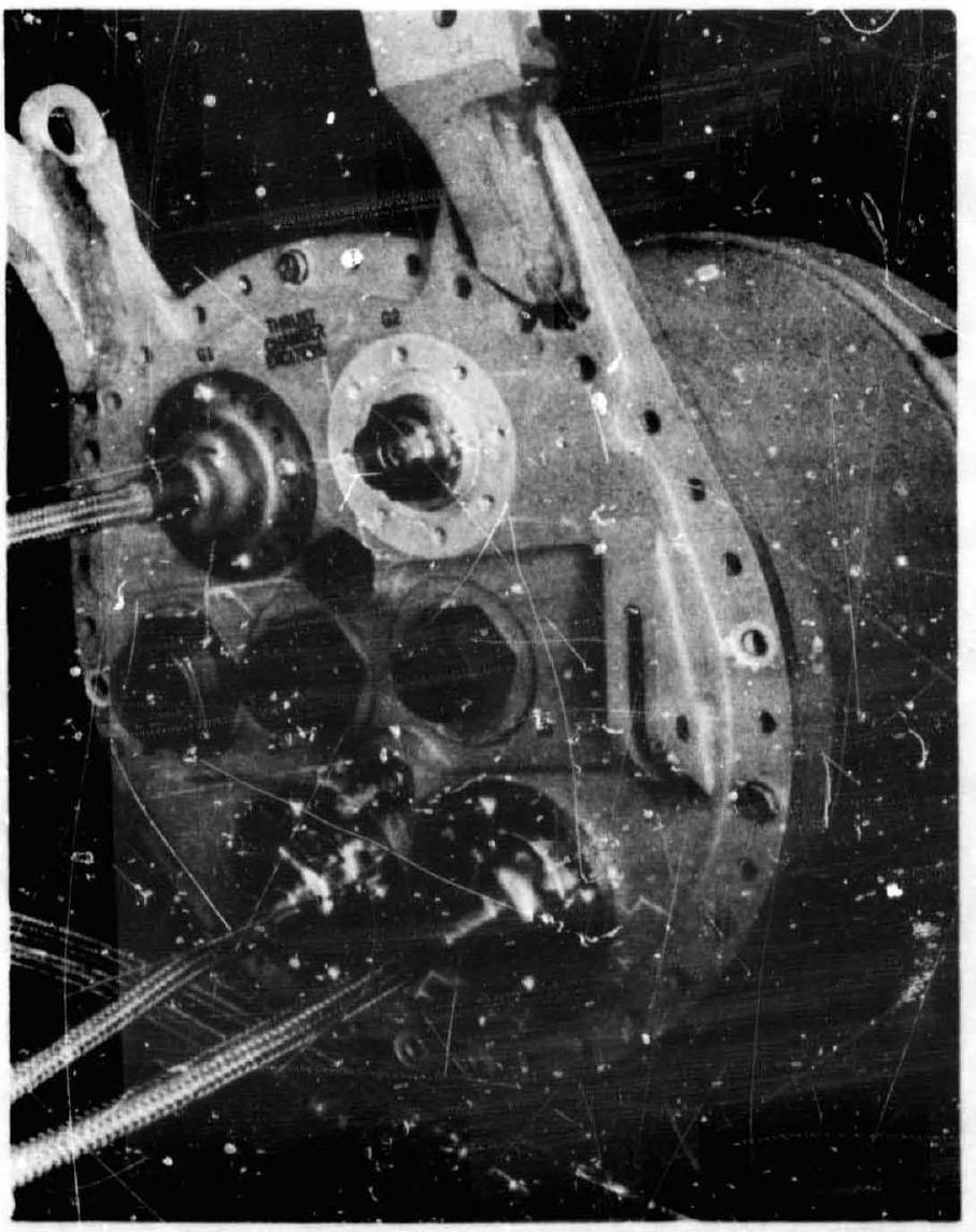 Figure 10-17.-Liquid rocket engine sequence controller.
houses 4 exciter coils for the spark plugs of thrust chamber and gas generator.
Position Indicators
To verify the position of a valve, or the proper installation of an igniter and similar mechanical conditions, position indicators are used. Most common types are:
Switches.-These are mainly used for "black and white" indications, such as "open" or "closed," "installed," "connection OK," etc. Numerous commercial products are qualified for rocket engine application and are available as compact, miniaturized, sealed units. They are part of the individual component designs and are described in other chapters. It will be the burden of the engine systems designer, however, to assure uniform standards, specifically for connectors. Position indicators of the switch type are instrumental for sequencing the start and stop of a liquid rocket engine.
Continuous indicators.-To know any intermediate position of a component, such as the angular position of a valve gate or the linear displacement of an actuator, continuously reading devices are required. Most widely used types are potentiometers and variable reluctance pickups. Potentiometers require a dc power source (typical: 5 volts), while inductive-type sensors require an ac power source (such as 400 volts). The output of both, often in combination with a bridge circuit, is fed to a telemetry and/or ground recording system. Indicators of the continuous type are predominantly used for instrumentation. It should be a goal to decrease their number as the development of the engine progresses.
Timers
During engine start and stop, timing devices are required for two principal reasons: correct sequencing of valve actuations and other events, and for monitoring the correctness of critical sequence times. In the latter case, they will inhibit progression of the sequence or initiate cutoff in case of malfunctions. A degree of timing can be accomplished by means of orifices and by sizing of volumes in the pneumatic or hydraulic activation system. All other timing must be provided by timers as part of the electrical system. For engine systems starting on the ground, these timers are mostly located in the ground control system. Several types of timers are commercially available for this application. They may be anotor driven or may use dashpots, springs, or other delaying devices for their function, usually with the capability for external adjustment within a specified range. If ground mounted, the timers' weight and size are of minor importance.
For systems starting at altitude, all timers required must be engine mounted (or at least stage provided). Here, weight and size do become important. Modifications of the solid-state switches described above, through addition of suitable capacitance/resistance circuits, have been successfully applied. As a rule, these timers are not adjustable once assembled, but require replacement of the entire module in case of timing changes.
Heaters
Ideally, all components of an engine system should be capable of operating reliably and unaided at all temperatures occurring during operation. In many applications, however, extreme temperature variations occur, due to the environment at high altitudes, or within an engine system, particularly within those using cryogenics. The development of components able to withstand these extremes without assistance would often be very costly or altogether impossible. Thus it is much simpler to reduce or eliminate the temperature extremes by suitable means. For some areas, mere insulation may be adequate. Others require heating (external means for cooling are rarely required for rocket engines, but are used for other vehicle systems). Bulk temperature conditioning is usually provided on static firing stands and within vehicles during standby by blowing preheated inert gases or air into the engine compartment. However, certain strategic components will require individual heating at all times after propellant loading. Of these, some may require this only through takeoff from a 28 volt dc ground source, if their heat capacit; keeps them sufficiently warm for their relatively short period of operation following heater disconnect. Other components, particularly those which have to operate during extended periods following takeoff, will require supply from an airborne power source, which is usually the main battery. Because of the relatively high power requirements for heaters airborne heating should be kept to a minimum. This can be accomplished by judicious placement oỉ components away from areas of extreme cold, and by insulation and isolation. For instance, a hydraulic pump attached to the auxiliary drive of a LOX pump, or the actuator of a cryogenic valve (see fig. 10-18, near center) may require drastically reduced heating, or none at all, if a heat barrier (gasketlike wafer of suitable material) is placed between connecting flanges. Furthermore, in the hydraulic system of an engine, heating requirements may be completely avoided if the hydraulic fluid is continuously circulated during standby.
For cases where electrical heaters must be applied, a number of types are available. A common one is the blanket heater, which is applied externally as a sleeve or cover, formfitted for best efficiency, and equipped with a thermostat.
In other applications, an immersed heater, i.e., a Calrod-type heating element cast or embedded into the component metal, is used, for instance, to protect a cryogenic pump bearing.
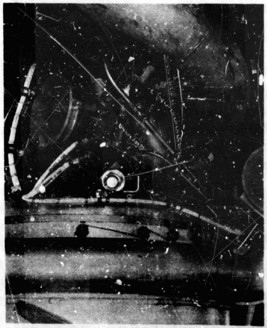 Figure 10-18.-Wire harness installation for main valve position switches.
Power Sources; Batteries
For its operation, a rocket engine electrical system requires power which is almost always supplied by the vehicle or from the ground. The engine designer need not concern himself with the power supply, except for the specification of requirements and provisions for connection. Frequently used voltages are:
28 -volt dc for heaters, control solenoids, relays, switches, igniter spark exciters, certain instrumentation (typical peakload: 2000 watts per engine) 5 -volt dc for instrumentation (potentiometers) 8 -volt dc for spark monitors (see ch. IV, spark plugs) 115 -volt, ac for instrumentation The required power is supplied directly from batteries for dc needs, or through converters for ac consumptions.
Miscellaneous Components
To complete an engine electrical system, a number of standard or special components are required: resistors, capacitors, diodes, terminal strips, connectors, and receptacles. All are commercially available, qualified for rocket engine use.
Connecting Wiring
The various subsystems of the engine electrical system must be connected by suitable wiring, which for proper mounting and clean routing is combined into one or several wire harnesses.
Figure shows portion of a harness installed on a liquid rocket engine. For manufacture, the engine systems designer must supply certain information. This is best combined into a single drawing, which contains the following information (fig. 10-19): (1) Wire list.-This list calls out each harness wire by number and lists its length. It also specifies the wire routing between plugs and/or receptacles. (2) Harness schematic.-For clarity, the schematic repeats in pictorial form most of the information supplied in the wire list, together with additional information. It also calls out the total length of wire required for material procurement purposes. (3) Physical routing diagram.-This diagram defines the branch points and their relative distance from the main plug or receptacle. It is usually difficult to determine the exact length of individual wires and of some of the branches on the drawing board. It is customary to finalize these dimensions on a mockup engine. For this reason, certain dimensions in the physical routing diagram are left blank and the total cable length is specified "as required."
For proper design of a rocket engine wire harness, the following must be considered:
Routing (minimum distance, weight, electrical resistance, interference) Secure clamping (safety, avoidance of wire chafing) Selection of attachment points (avoidance of special brackets) Adequate support (harness weight, vehicle acceleration) Moisture protection (potting, sheathing) Heat protection (routing, wrapping) Arcing protection (component selection, dryness) Flexibility (installation, stiffness versus gimbal load) Connectors must have means to secure them to prevent accidental disconnect. This has been done with the connectors shown in figure 10-18 by means of threaded sleeves, further secured by safety wires. To prevent incorrect connections and/or damage to the connector pins, "clocking" by means of key and slot, of connectors and receptacles, is highly recommended.
In addition to the cabling required to interconnect the various engine electrical subsystems, other cables are required to link these systems to the vehicle systems. This includes wiring for power supply, controls (start and stop, PU, throttling, etc.), instrumentation and checkout circuits. To facilitate engine installation and line connections, these wires are combined into trunks, each terminating in connectors which must have, at the proper location, a mating counterpart on the vehicle. For the stage, a "J-Box" (junction box) is recommended, into which are plugged both the engine and the stage systems connectors. On the inside, the box permits easy and environment protected redistribution of incoming and outgoing wires to assigned connectors. Figure 10-20 shows a typical block
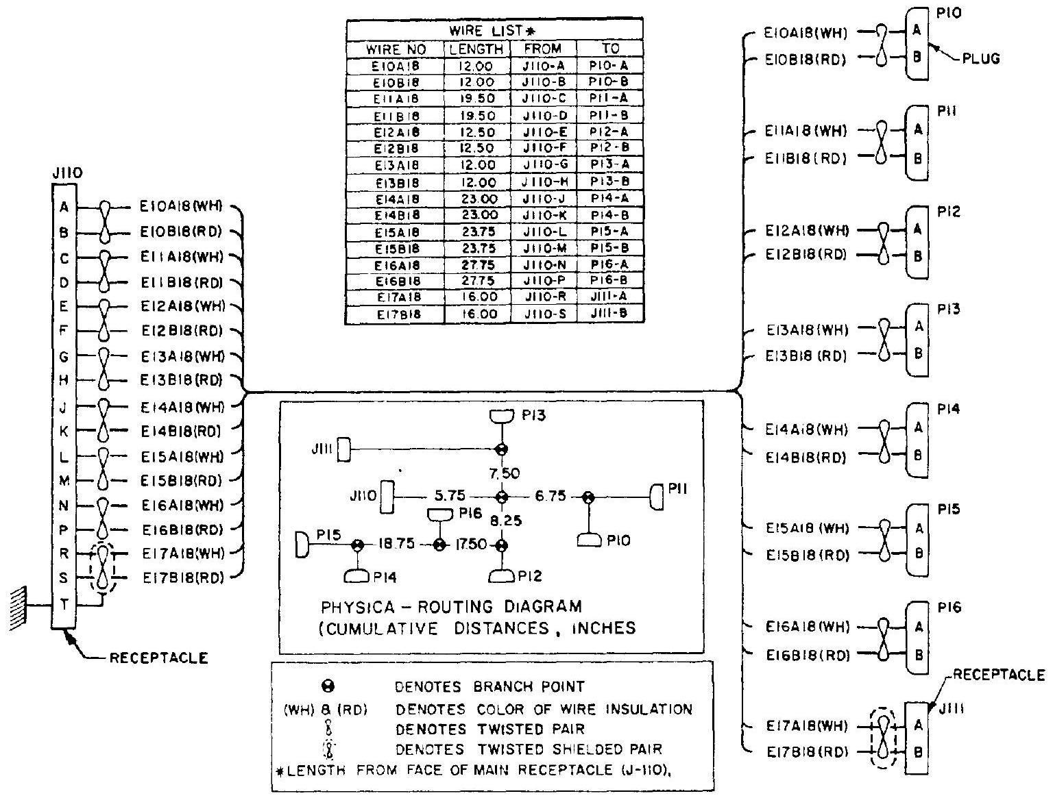 Figure 10-19.-Typical rocket engine wire harness diagram.
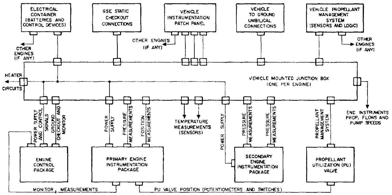 Figure 10-20.-Typical block diagram, engine to vehicle electrical connections.
diagram for the principal electrical connections between engine and vehicle. Flexibility of these trunks usually poses no problem in view of the relatively small engine deflection during gimbaling, but if heavy sheathing (armor) is used, care must be taken to avoid excessive loads to the gimbal actuators or damage to the cables.